Overview
The Romi firmware is organized around a cooperative multitasking architecture, following the structure introduced in ME 405. Rather than implementing all behavior in a single monolithic loop, the system is decomposed into independent tasks responsible for sensing, control, actuation, estimation, and communication.
This architecture allows time-critical operations to execute deterministically while higher-level logic runs concurrently without blocking. Tasks communicate exclusively through shared variables and queues, which enforces clear interfaces and simplifies debugging and validation.
High-Level Task Architecture
The figure below shows the high-level task structure used in the final system and the flow of information between tasks.
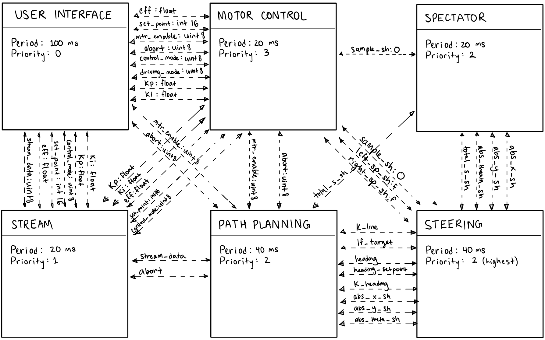
Each task executes periodically under control of the cooperative scheduler. Task periods were selected based on the timing requirements of each subsystem, balancing responsiveness with computational load.
Task Responsibilities
The major tasks in the final system are summarized below.
- Motor Task
Applies PWM effort commands and direction signals to the motor drivers. This task enforces bounded effort commands and explicit enable/disable behavior to ensure safe startup and shutdown. - Encoder Task
Reads quadrature encoder counts using hardware timer encoder mode and computes wheel position and velocity. This task provides the primary feedback signal for closed-loop motor control. - Velocity Control Task
Implements independent PI controllers for the left and right wheels. Encoder-derived velocity measurements are compared against commanded setpoints, and corrective motor efforts are generated. - Line Sensor Task
Samples the reflectance sensor array using ADC inputs and computes a line position error. Sensor processing is decoupled from control to allow tuning and validation in isolation. - Steering / Line-Following Task
Implements the outer-loop line-following logic. Reflectance sensor measurements are converted into steering corrections, which are translated into differential wheel velocity commands for the inner velocity control loops. - Odometry (Spectator) Task
Integrates incremental wheel motion to estimate total arc length traveled, absolute position, and heading. This task provides higher-level motion information without influencing control behavior directly. - Streaming / Communication Task
Streams selected internal variables to a PC in real time for diagnostics and visualization. Streaming is enabled by default and can be toggled from the PC interface.
Optional or experimental tasks, such as state estimation and path planning, are retained in the repository but are not enabled in the final configuration.
Inter-Task Communication
Tasks exchange data using thread-safe shared variables and queues rather than direct function calls. This design choice provides several advantages:
- Prevents unintended coupling between tasks
- Allows each task to run at an appropriate period
- Simplifies debugging by isolating faults to individual subsystems
- Avoids blocking behavior in time-critical tasks
Low-bandwidth, frequently accessed values (e.g., velocity setpoints, measured velocities) are communicated using shared variables, while streamed data is handled using queues.
Scheduling Strategy
A cooperative scheduler is used to manage task execution. Each task yields control back to the scheduler after completing a bounded amount of work. This ensures that no single task can monopolize CPU time and that all tasks execute predictably.
Task periods were selected based on subsystem requirements:
- Fast update rates for encoder reading and motor control
- Moderate rates for line sensing and steering logic
- Lower rates for streaming and diagnostic output
This approach provided sufficient determinism for closed-loop control while remaining simple to reason about and debug.
Discussion
The task-based architecture proved critical to the success of the project. Separating sensing, control, estimation, and communication into independent tasks made it possible to validate each subsystem incrementally before full system integration.
In practice, overall system performance was limited less by control structure and more by measurement quality and timing consistency. The cooperative multitasking framework made these limitations visible and manageable, reinforcing the importance of architecture in embedded system design.